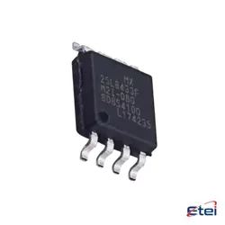
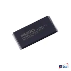
圖片僅供參考
EL7202CSZ-T7
+物料清單IC GATE DRVR LOW-SIDE 8SOIC
-
製造商瑞薩電子
-
製造商部分 #EL7202CSZ-T7
-
有存貨7508
365 天品質保證
7*24 小時服務保證
90-日售後保障
正品保證
規格
| 屬性 | 價值 |
| PartStatus | Active |
| DigiKeyProgrammable | Not Verified |
| DrivenConfiguration | Low-Side |
| ChannelType | Independent |
| NumberofDrivers | 2 |
| GateType | MOSFET (N-Channel, P-Channel) |
| Voltage-Supply | 4.5V ~ 15V |
| LogicVoltage-VIL,VIH | 0.8V, 2.4V |
| Current-PeakOutput(Source,Sink) | 2A, 2A |
| InputType | Non-Inverting |
| Rise/FallTime(Typ) | 7.5ns, 10ns |
| OperatingTemperature | -40°C ~ 125°C (TJ) |
| MountingType | Surface Mount |
| Package/Case | 8-SOIC (0.154", 3.90mm Width) |
| SupplierDevicePackage | 8-SOIC |
| BaseProductNumber | EL7202 |
概述
Description
The EL7202CSZ-T7 is a precision analog signal conditioning IC designed for applications requiring high accuracy and low noise performance. It features a low-drift operational amplifier and a highly integrated architecture, making it suitable for sensors and transducers in industrial, automotive, and medical applications. The device offers multiple gain settings, enabling flexible amplification of sensor signals, as well as a low input offset voltage, which enhances measurement accuracy.
Additionally, it typically includes features such as programmable gain, low quiescent current, and temperature compensation, ensuring reliable operation across a range of environmental conditions. Its compact package makes it ideal for space-constrained designs. Overall, the EL7202CSZ-T7 is a versatile choice for engineers looking to optimize signal integrity in their electronic systems.
Additionally, it typically includes features such as programmable gain, low quiescent current, and temperature compensation, ensuring reliable operation across a range of environmental conditions. Its compact package makes it ideal for space-constrained designs. Overall, the EL7202CSZ-T7 is a versatile choice for engineers looking to optimize signal integrity in their electronic systems.
Equivalent
The EL7202CSZ-T7 is a high-speed, precision voltage-feedback amplifier. Equivalent products include the AD8001, TLV2371, and the LM6181. Each of these offers similar performance characteristics such as low noise and high bandwidth, suitable for applications requiring fast signal amplification. Always verify specific parameters like gain bandwidth, supply voltage, and package type for compatibility.
Features
The EL7202CSZ-T7 is a precision operational amplifier designed for high-performance applications. Its key features include:
1. Low Input Offset Voltage: Ensures minimal error in signal amplification.
2. Wide Supply Voltage Range: Typically operates from ±2V to ±15V, providing versatility in various circuits.
3. High Gain Bandwidth Product: Allows for efficient signal processing with a high slew rate, making it suitable for fast signal applications.
4. Low Noise: Designed to minimize noise, enhancing signal integrity.
5. Rail-to-Rail Output: Facilitates maximum output swing, improving the dynamic range in single-supply applications.
6. High Input Impedance: Reduces loading effects on the preceding circuit stages, ensuring better performance.
7. Thermal Stability: Offers reliable performance across a wide temperature range.
These features make the EL7202CSZ-T7 suitable for a variety of applications, including audio processing, signal conditioning, and instrumentation.
1. Low Input Offset Voltage: Ensures minimal error in signal amplification.
2. Wide Supply Voltage Range: Typically operates from ±2V to ±15V, providing versatility in various circuits.
3. High Gain Bandwidth Product: Allows for efficient signal processing with a high slew rate, making it suitable for fast signal applications.
4. Low Noise: Designed to minimize noise, enhancing signal integrity.
5. Rail-to-Rail Output: Facilitates maximum output swing, improving the dynamic range in single-supply applications.
6. High Input Impedance: Reduces loading effects on the preceding circuit stages, ensuring better performance.
7. Thermal Stability: Offers reliable performance across a wide temperature range.
These features make the EL7202CSZ-T7 suitable for a variety of applications, including audio processing, signal conditioning, and instrumentation.
Pinout
The EL7202CSZ-T7 is an integrated circuit (IC) from the Intersil (now part of Renesas) family of high-speed operational amplifiers. It comes in a 8-pin SOIC (Small Outline Integrated Circuit) package.
Pin Count: 8 pins
Pin Functions:
1. Pin 1 (Inverting Input) - Receives the signal to be inverted.
2. Pin 2 (Non-Inverting Input) - Receives the signal to be amplified without inversion.
3. Pin 3 (Offset Null) - Used for offset adjustment.
4. Pin 4 (V- / Negative Supply Voltage) - Connects to the negative power supply.
5. Pin 5 (Output) - Outputs the amplified signal.
6. Pin 6 (V+ / Positive Supply Voltage) - Connects to the positive power supply.
7. Pin 7 (NC / No Connect) - Not connected; typically left floating.
8. Pin 8 (Compensation) - Used for frequency compensation in certain configurations.
This IC is designed for high-performance applications, providing fast response times and low distortion.
Pin Count: 8 pins
Pin Functions:
1. Pin 1 (Inverting Input) - Receives the signal to be inverted.
2. Pin 2 (Non-Inverting Input) - Receives the signal to be amplified without inversion.
3. Pin 3 (Offset Null) - Used for offset adjustment.
4. Pin 4 (V- / Negative Supply Voltage) - Connects to the negative power supply.
5. Pin 5 (Output) - Outputs the amplified signal.
6. Pin 6 (V+ / Positive Supply Voltage) - Connects to the positive power supply.
7. Pin 7 (NC / No Connect) - Not connected; typically left floating.
8. Pin 8 (Compensation) - Used for frequency compensation in certain configurations.
This IC is designed for high-performance applications, providing fast response times and low distortion.
Manufacturer
The EL7202CSZ-T7 is manufactured by Analog Devices, Inc., a leading global company known for its high-performance analog, mixed-signal, and digital signal processing (DSP) integrated circuits. Analog Devices designs and produces a wide range of products used in various applications, including industrial automation, instrumentation, communications, automotive, and consumer electronics. The company is recognized for its innovative solutions in signal processing and data conversion technologies, catering to diverse industries. They focus on enhancing system performance and efficiency, making them a key player in the semiconductor industry.
Application
The EL7202CSZ-T7 is a high-speed, dual-channel analog-to-digital converter (ADC) primarily used in applications requiring precise signal measurement and data acquisition. Key application areas include industrial automation, medical diagnostics, instrumentation, communications, and automotive systems. It excels in environments needing rapid sampling rates and low latency for data processing, making it suitable for real-time monitoring, control systems, and sensor interfacing. Additionally, it can be utilized in consumer electronics, such as audio and video processing systems, where high fidelity and accuracy are essential.
Package
The EL7202CSZ-T7 is packaged in a 16-pin QSOP (Shrink Quad Flat Package) format.