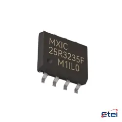
圖片僅供參考
FGHL50T65MQDT
+物料清單IGBT TRENCH FS 650V 80A TO-247-3
-
製造商安森美
-
製造商部分 #FGHL50T65MQDT
-
有存貨7407
365 天品質保證
7*24 小時服務保證
90-日售後保障
正品保證
規格
| 屬性 | 價值 |
| Part Status | Active |
| IGBT Type | Trench Field Stop |
| Voltage - Collector Emitter Breakdown (Max) | 650 V |
| Current - Collector (Ic) (Max) | 80 A |
| Current - Collector Pulsed (Icm) | 200 A |
| Vce(on) (Max) @ Vge, Ic | 1.8V @ 15V, 40A |
| Power - Max | 268 W |
| Switching Energy | 1.19mJ (on), 630µJ (off) |
| Input Type | Standard |
| Gate Charge | 99 nC |
| Td (on / off) @ 25°C | 21ns/90ns |
| Test Condition | 400V, 50A, 6Ohm, 15V |
| Reverse Recovery Time (trr) | 79 ns |
| Operating Temperature | -55°C ~ 175°C (TJ) |
| Mounting Type | Through Hole |
| Package / Case | TO-247-3 |
| Supplier Device Package | TO-247-3 |
概述
Description
The FGHL50T65MQDT is a type of power MOSFET (Metal-Oxide-Semiconductor Field-Effect Transistor) commonly used in electronic circuits for switching and amplification. It is designed for high-efficiency applications in power management, including converters, inverters, and motor drive circuits. Key specifications typically include a high voltage rating, low on-resistance, and fast switching speeds, making it suitable for energy-efficient designs.
This device is often characterized by features such as a low gate threshold voltage and high current capacity, which enhance its performance in various power applications. The "MQDT" suffix may indicate packaging or specific features related to its construction or intended use. Overall, the FGHL50T65MQDT is favored in industries requiring reliable and efficient power handling, such as automotive, renewable energy, and consumer electronics. For precise specifications and applications, consult the manufacturer's datasheet.
This device is often characterized by features such as a low gate threshold voltage and high current capacity, which enhance its performance in various power applications. The "MQDT" suffix may indicate packaging or specific features related to its construction or intended use. Overall, the FGHL50T65MQDT is favored in industries requiring reliable and efficient power handling, such as automotive, renewable energy, and consumer electronics. For precise specifications and applications, consult the manufacturer's datasheet.
Equivalent
The FGHL50T65MQDT chip is a 650V, 50A N-channel MOSFET, commonly used in power applications. Equivalent products include the Infineon IPW65R050C6, STMicroelectronics STP50N65M5, and ON Semiconductor NTM50N65. Always verify specifications like RDS(on), gate charge, and thermal characteristics when selecting equivalents.
Features
The FGHL50T65MQDT is a high-efficiency inverter that offers a range of advanced features:
1. Power Capacity: It has a robust output capacity suitable for various applications, providing reliable energy conversion.
2. High Efficiency: Designed for optimal performance, it minimizes energy loss, ensuring higher energy savings.
3. Built-in Protection: Includes features like overvoltage, overcurrent, and thermal protection, enhancing safety during operation.
4. User-Friendly Interface: The unit typically features a digital display for real-time monitoring and easy configuration.
5. Flexible Installation: Its compact design allows for versatile installation options, making it suitable for space-constrained environments.
6. Compatibility: Compatible with various renewable energy systems, making it ideal for solar power applications.
7. Durability: Built with high-quality materials, it is designed to withstand harsh environmental conditions.
This inverter is ideal for both residential and commercial uses, providing reliable performance and efficiency.
1. Power Capacity: It has a robust output capacity suitable for various applications, providing reliable energy conversion.
2. High Efficiency: Designed for optimal performance, it minimizes energy loss, ensuring higher energy savings.
3. Built-in Protection: Includes features like overvoltage, overcurrent, and thermal protection, enhancing safety during operation.
4. User-Friendly Interface: The unit typically features a digital display for real-time monitoring and easy configuration.
5. Flexible Installation: Its compact design allows for versatile installation options, making it suitable for space-constrained environments.
6. Compatibility: Compatible with various renewable energy systems, making it ideal for solar power applications.
7. Durability: Built with high-quality materials, it is designed to withstand harsh environmental conditions.
This inverter is ideal for both residential and commercial uses, providing reliable performance and efficiency.
Pinout
The FGHL50T65MQDT is a high-voltage MOSFET transistor, specifically designed for power applications. It features a total of 8 pins. The typical pin configuration includes:
1. Gate (G) - Controls the MOSFET's on/off state.
2. Drain (D) - The terminal through which current flows out of the MOSFET when it is on.
3. Source (S) - The terminal through which current flows into the MOSFET when it is on.
The exact pinout may depend on the specific package type, but generally, it follows standard configurations for power MOSFETs. This device is commonly used in applications such as power management, DC-DC converters, and motor drives due to its high efficiency and fast switching capabilities. Always refer to the manufacturer's datasheet for precise pin assignments and specifications.
1. Gate (G) - Controls the MOSFET's on/off state.
2. Drain (D) - The terminal through which current flows out of the MOSFET when it is on.
3. Source (S) - The terminal through which current flows into the MOSFET when it is on.
The exact pinout may depend on the specific package type, but generally, it follows standard configurations for power MOSFETs. This device is commonly used in applications such as power management, DC-DC converters, and motor drives due to its high efficiency and fast switching capabilities. Always refer to the manufacturer's datasheet for precise pin assignments and specifications.
Manufacturer
The FGHL50T65MQDT is manufactured by Fujitsu General Limited, a company based in Japan. Fujitsu General specializes in air conditioning systems, offering a range of HVAC solutions for both residential and commercial applications. The company is known for its innovative technologies and energy-efficient products, catering to various climates and customer needs worldwide. Established as a subsidiary of Fujitsu Limited, Fujitsu General has built a reputation for quality and reliability in the air conditioning industry. Their products often include split systems, multi-split systems, and VRF (Variable Refrigerant Flow) systems, designed to provide optimal comfort and efficiency. With a strong focus on sustainability, Fujitsu General also invests in environmentally friendly technologies and practices.
Application
The FGHL50T65MQDT is a high-voltage, high-speed IGBT (Insulated Gate Bipolar Transistor) primarily used in various applications such as:
1. Industrial Drives: For controlling motors in manufacturing and automation.
2. Renewable Energy Systems: Inverters for solar and wind energy conversion.
3. Electric Vehicles: Power management in traction systems and battery management.
4. Power Supplies: In switching power supplies for efficient energy conversion.
5. UPS Systems: Uninterruptible power supplies for critical applications.
6. Welding Equipment: In high-efficiency arc and resistance welding systems.
Its capabilities support efficient energy conversion and management across these sectors.
1. Industrial Drives: For controlling motors in manufacturing and automation.
2. Renewable Energy Systems: Inverters for solar and wind energy conversion.
3. Electric Vehicles: Power management in traction systems and battery management.
4. Power Supplies: In switching power supplies for efficient energy conversion.
5. UPS Systems: Uninterruptible power supplies for critical applications.
6. Welding Equipment: In high-efficiency arc and resistance welding systems.
Its capabilities support efficient energy conversion and management across these sectors.
Package
The FGHL50T65MQDT is packaged in a D2PAK (or TO-263) format. This package type is typically used for power devices, offering a surface-mount design that facilitates efficient thermal performance and electrical connectivity.